

Manual Floor Plan Creation: A Step-by-Step Tutorial
Manual Floor Plan Creation: To guide you through the process, this article will walk through a step-by-step tutorial for creating floor plans manually. Let’s take a closer look at each part of this blog.
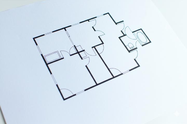
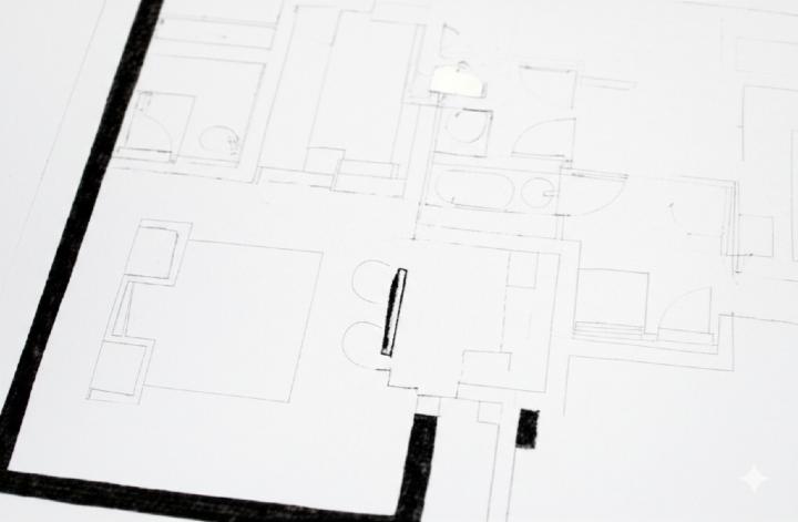
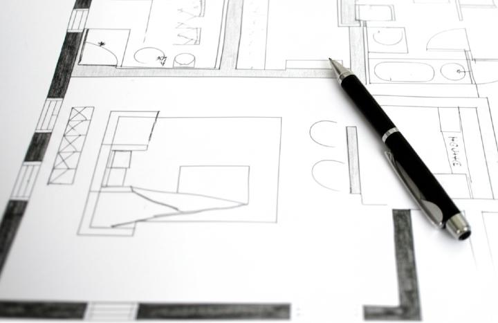
Creating a floor plan by hand can be a rewarding and insightful process. It allows for a deeper understanding of space and design. This tutorial will guide you through the process, explaining the necessary equipment, scaling methods, and step-by-step instructions.
Prerequisites: Gathering Your Tools
Before you begin, ensure you have the following equipment:
1) Paper: Large sheets of good quality tracing paper or graph paper (preferably with a light grid). Tracing paper allows for easy layering and corrections.

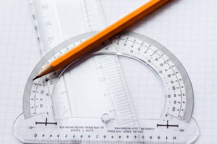
2) Pencils: A range of pencils with different hardness (e.g., 2H for light construction lines, HB or F for final lines). Mechanical pencils with consistent lead thickness are also useful.

3) Eraser: A good quality soft eraser that doesn’t smudge. A kneaded eraser is also handy for lifting faint lines.
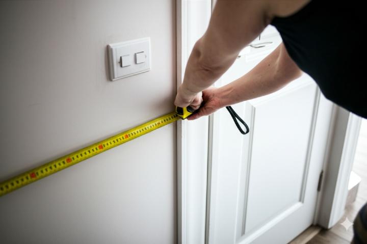
4) Measuring Tape: A long and accurate measuring tape (preferably imperial and metric).

5) Engineering Scale: This is crucial for drawing accurately to scale. It has multiple scales along its edges, allowing you to represent larger dimensions on paper.
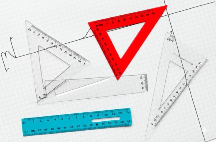
6) Ruler or Straight Edge: For drawing straight lines. A longer ruler (at least 12 inches or 30 cm) is recommended.

7) Triangles (30-60-90 and 45-45-90): Useful for drawing accurate perpendicular and angled lines.
8) Compass: For drawing circles and arcs (useful for representing door swings).

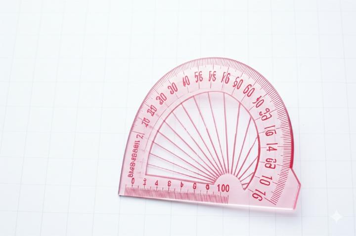
9) Protractor: For measuring and drawing angles.
10) Clips or Drafting Tape: To secure your paper to a flat surface.

Understanding Scaling and Using an Engineering Scale
What is Scaling?
Scaling is the process of representing real-world objects and spaces at a reduced or enlarged size on a drawing. For a floor plan, you’ll almost always be using a reduction scale, meaning a certain unit of measurement in the real space will be represented by a smaller unit on your drawing.
Choosing a Scale:
The scale you choose depends on the size of the area you’re planning and the size of your paper. Common architectural scales are:
1/4″ = 1′ – 0″ (Quarter inch equals one foot) – Good for smaller residential spaces.
1/8″ = 1′ – 0″ (Eighth inch equals one foot) – Suitable for larger residential or smaller commercial spaces.
1/16″ = 1′ – 0″ (Sixteenth inch equals one foot) – Used for very large buildings or site plans.
Metric scales are also common, such as 1:50, 1:100, 1:200, etc. In a 1:100 scale, 1 unit on the drawing represents 100 of the same units in reality.
Using an Engineering Scale:
An engineering scale is different from a standard ruler. It features multiple scales along its triangular or flat edges. Each scale is marked with numbers that indicate how many feet (or meters, depending on the type of scale) are represented by one inch (or centimeter) on the drawing.
How to Read an Engineering Scale (Imperial Example – 1/4″ = 1′-0″):
Locate the desired scale: Find the edge of the scale marked with the chosen scale (e.g., 1/4″).
Identify the zero point: The zero point for that scale is usually at one end or near the middle with markings extending in both directions.
Measure feet: The large numbers along the scale represent whole feet. For the 1/4″ = 1′-0″ scale, each quarter inch on the scale represents one foot in reality.
Measure inches (fractions of a foot): To the right of the zero point, there are smaller subdivisions representing inches or fractions of a foot. These are crucial for accurate measurements. On the 1/4″ scale, these smaller marks typically represent inches (e.g., 1/2″, 1″, 2″, up to 11″).
Example: If a wall is 15 feet and 6 inches long and you are using a 1/4″ = 1′-0″ scale:
Locate the ’15’ mark on the 1/4″ scale.
Count six of the smaller inch subdivisions to the right of the zero point.
The total distance on your drawing will represent 15′ – 6″.
Stage-by-Stage Instructions for Manual Floor Plan Creation:
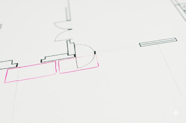
Stage 1: Preliminary Sketch and Measurements
1) Sketch the Outline: Lightly sketch the approximate shape of the space you are planning to draw. This doesn’t need to be to scale yet, but it helps visualize the layout.
2) Take Accurate Measurements: Using your measuring tape, measure all the walls, openings (doorways, windows), and the overall dimensions of the space. Note down these measurements clearly. Measure the thickness of walls and the sizes of windows and doors.
Stage 2: Drawing the Exterior Walls
1) Choose Your Scale: Decide on an appropriate scale based on the size of your space and paper. Write the scale clearly on your drawing.
2) Start with a Baseline: On your paper, use a light pencil (2H) and your straight edge to draw a horizontal or vertical line representing one of the main exterior walls. Use your engineering scale to mark the length of this wall according to your chosen scale.
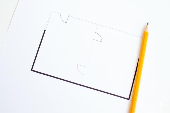
3) Draw Adjacent Walls: Using your measurements and the engineering scale, draw the walls connected to your baseline. Use your triangles to ensure the corners are square (90 degrees) unless the building has angled walls (which you would have measured). Remember to account for wall thickness. Draw all construction lines lightly.

4) Complete the Exterior Outline: Continue drawing all the exterior walls, constantly referring to your measurements and using the engineering scale for accurate lengths. Double-check that the final wall connects correctly to your starting point.

Stage 3: Drawing Interior Walls
1) Locate Interior Walls: Using your measurements from the exterior walls, lightly mark the starting and ending points of the interior walls on your drawing using the engineering scale.
2) Draw Interior Walls: Connect the marked points with light lines using your straight edge, ensuring the walls are straight and perpendicular to the walls they connect to (unless otherwise measured). Remember to maintain consistent wall thickness throughout your drawing.

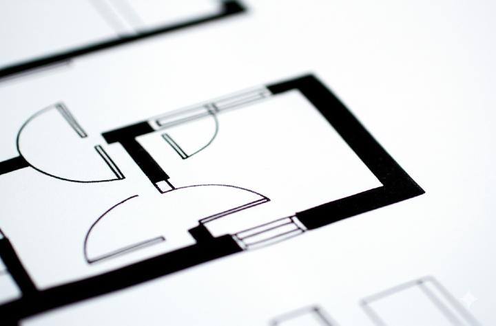
Stage 4: Adding Doors and Windows
1) Locate Openings: Using your measurements, mark the positions of doors and windows on the appropriate walls with light lines. Measure the width of the openings.
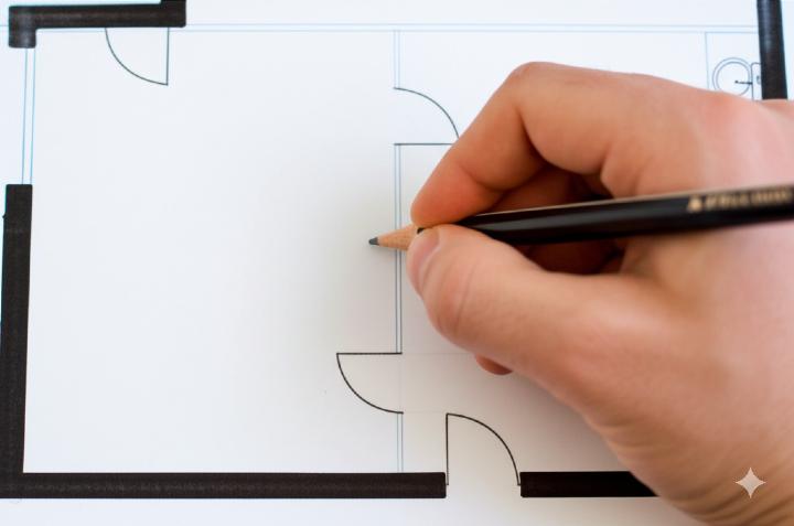
2) Draw Doors: Represent doors as a gap in the wall. Draw a thin rectangle representing the door itself, hinged on one side of the opening. Use your compass to draw a quarter-circle arc showing the direction of the door swing. The radius of the arc should be equal to the width of the door.

3) Draw Windows: Represent windows as a gap in the wall. Draw two or more parallel lines within the opening to indicate the window panes.

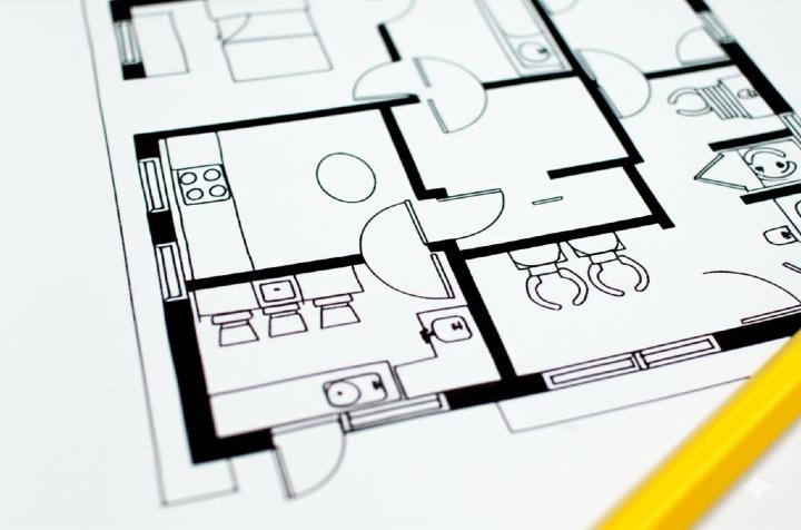
Stage 5: Adding Fixtures and Features (Optional)
1) Sketch Basic Fixtures: Lightly sketch in the approximate locations of major fixtures like sinks, toilets, showers, bathtubs, kitchen counters, and appliances. You don’t need intricate details at this stage, just basic shapes to represent their placement and size relative to the walls and each other. Refer to standard fixture sizes if needed.
2) Represent Stairs (if applicable): Draw a series of rectangles representing the steps, with an arrow indicating the direction of ascent. Label “UP” or “DN”.

3) Indicate Built-in Features: Show elements like closets, fireplaces, or niches with appropriate lines and symbols.
Stage 6: Darkening Lines and Adding Details
1) Review and Correct: Carefully review your entire drawing, comparing it to your measurements and preliminary sketch. Make any necessary corrections using your eraser. Ensure all walls are parallel or perpendicular where they should be and that all dimensions are consistent with your chosen scale.

2) Darken Final Lines: Once you are satisfied with the accuracy of your light construction lines, use a slightly softer pencil (HB or F) to carefully trace over the final wall lines, door swings, and window representations. This will make your floor plan clearer and easier to read.
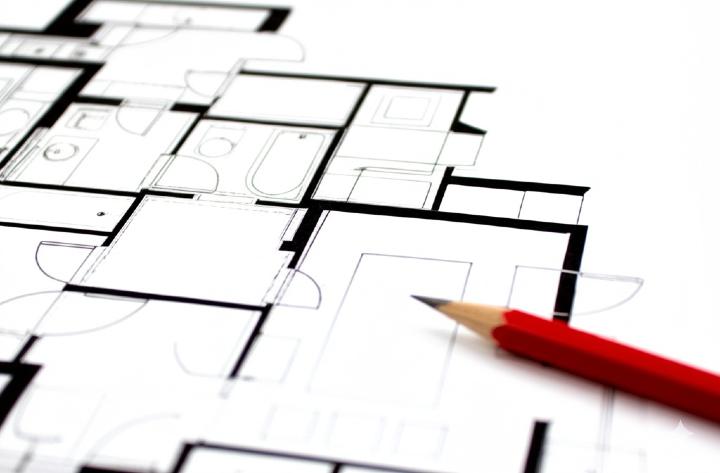
3) Add Labels and Annotations: Clearly label each room (e.g., “Living Room,” “Bedroom,” “Kitchen”). You can also add dimensions if needed, either directly on the walls or with extension lines and dimension lines. Include the chosen scale of your drawing.

Stage 7: Final Touches
1) Erase Construction Lines: Carefully erase any remaining light construction lines that are no longer needed.
2) Review for Clarity: Take a final look at your floor plan to ensure it is clear, accurate, and easy to understand.
Congratulations! You have now created a floor plan manually. This process requires patience and attention to detail, but it provides a valuable skill in understanding spatial relationships and design. Remember to practice and don’t be afraid to make mistakes – they are part of the learning process.
In Conclusion: Manual Floor Plan Creation
We hope this tutorial has provided you with a clear and practical understanding of Manual Floor Plan Creation. Now, you can confidently apply these techniques to your own projects. Remember to take your time and pay close attention to the details. We’re confident you’ll create excellent floor plans.
Similar useful tutorials:
How to Draw a 50 x 30 Floor Plan in CorelDRAW
Downloads:
Floor Plan Word Template (download)